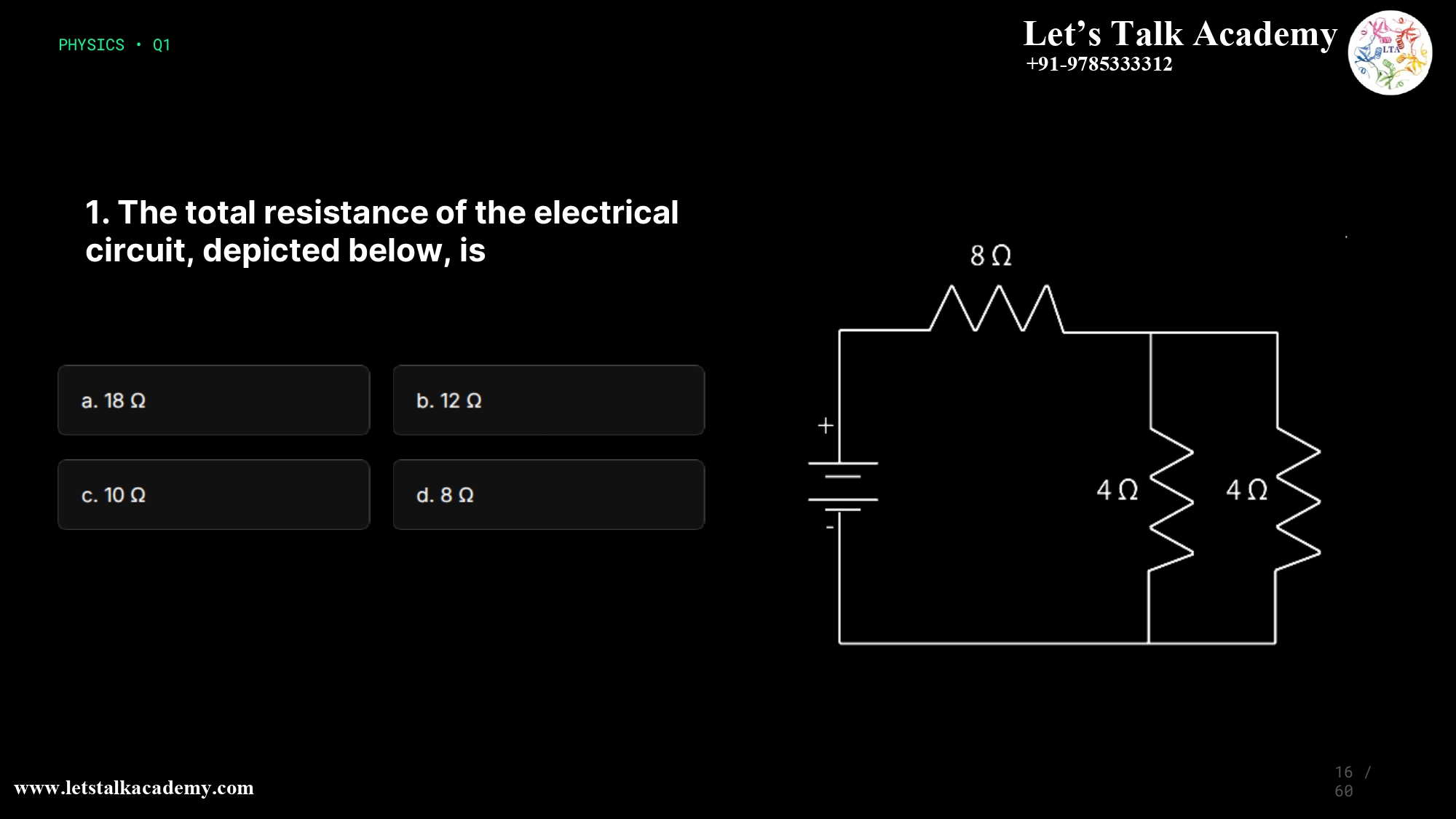
16.The total resistance of the electrical circuit, depicted below, is
a. 18 Ω
b. 12 Ω
c. 10 Ω
d. 8 Ω
How to Calculate Total Resistance in Series-Parallel Circuits: Step-by-Step Solution with Option Analysis
Introduction
Understanding how to calculate total resistance in electrical circuits is a fundamental concept in physics and electrical engineering. When resistors are combined in series and parallel configurations within a single circuit, you need to apply specific mathematical rules to determine the equivalent resistance.
This comprehensive guide walks through a practical circuit problem, explains each calculation step, and analyzes all answer options to help you master this critical physics skill. Whether you’re preparing for competitive exams like CSIR NET, JEE, or just learning circuit basics, this detailed walkthrough will strengthen your understanding of resistance calculations in combination circuits.
Understanding Circuit Configuration Basics
Series Circuits
When resistors are connected in a series circuit, they are arranged one after another in a single path. The same current flows through all resistors sequentially. To find the total resistance in a series circuit, you simply add all individual resistances:
Formula: \( R_{total} = R_1 + R_2 + R_3 + \ldots + R_n \)
Parallel Circuits
In a parallel circuit, resistors are connected across multiple paths between two common nodes. The voltage across each resistor is the same, but the current divides among different paths. The equivalent resistance is calculated using the reciprocal formula:
Formula: \( \frac{1}{R_{total}} = \frac{1}{R_1} + \frac{1}{R_2} + \frac{1}{R_3} + \ldots + \frac{1}{R_n} \)
Key point: the combined resistance is always less than the smallest individual resistance.
Combination Circuits
When a circuit contains both series and parallel resistors, it’s called a combination circuit or mixed circuit. Resistance for each configuration must be calculated separately and then combined appropriately.
Circuit Diagram Analysis
The circuit consists of:
- A battery (voltage source)
- One 8Ω resistor in the main series path
- Two 4Ω resistors connected in parallel
This is a classic combination circuit requiring two calculation steps: find the parallel equivalent, then add the series resistor.
Step-by-Step Solution
Step 1: Calculate the Equivalent Resistance of the Parallel Resistors
Using the parallel resistance formula:
\( \frac{1}{R_{parallel}} = \frac{1}{4} + \frac{1}{4} = \frac{1}{2} \)
\( R_{parallel} = 2Ω \)
Shortcut: Two equal resistors in parallel always have half the resistance of one: \( R_{parallel} = \frac{R}{2} \).
Step 2: Calculate the Total Equivalent Resistance
Now add the series resistor:
\( R_{total} = 8 + 2 = 10Ω \)
Answer Options Analysis
Option A: 18Ω
This value has no logical derivation from circuit parameters. It results from a fundamental misunderstanding of configuration principles.
Verdict: ✗ INCORRECT
Option B: 12Ω
This results from common mistakes such as adding only one parallel resistor to the series resistor (8 + 4 = 12Ω) or ignoring the second resistor.
Verdict: ✗ INCORRECT
Option C: 10Ω
This is the correct answer. Proper calculation gives:
\( R_p = 2Ω \), and \( R_{total} = 8 + 2 = 10Ω \).
Physical interpretation: the circuit behaves like a single resistor of 10Ω connected to the battery.
Verdict: ✓ CORRECT
Option D: 8Ω
This answer ignores the parallel branch entirely. Parallel combinations can’t be omitted since they always reduce total resistance.
Verdict: ✗ INCORRECT
Key Formulas for Exam Success
| Configuration | Formula | Use Case |
|---|---|---|
| Series Resistors | \( R_t = R_1 + R_2 + R_3 + \ldots + R_n \) | Resistors connected end-to-end |
| Parallel Resistors | \( \frac{1}{R_t} = \frac{1}{R_1} + \frac{1}{R_2} + \ldots + \frac{1}{R_n} \) | Across same two nodes |
| Two Parallel (Shortcut) | \( R_t = \frac{R_1 \times R_2}{R_1 + R_2} \) | Exactly two resistors |
| Identical Parallel | \( R_t = \frac{R}{n} \) | n identical resistors of value R |
Common Mistakes to Avoid
- Failing to identify series vs. parallel correctly.
- Adding all resistances directly without checking configuration.
- Forgetting to invert the reciprocal in parallel formulas.
- Mixing formulas for different configurations.
- Ignoring branches or making arithmetic errors with fractions.
Practical Tips for Circuit Problems
- Simplify step by step by solving one section at a time.
- Use visual simplification diagrams to verify your steps.
- Check consistency in fraction or decimal usage.
- Verify the logical range of your result.
- Practice different combinations to strengthen concept recognition.
Conclusion
The correct answer is Option C: 10Ω. This solution emphasizes analyzing the circuit properly, applying appropriate formulas, and systematically reducing complex circuits to simpler equivalents.
By mastering these rules, you can confidently solve any series-parallel resistance calculation problem in exams or real-world scenarios.


